Integrating Fortinet SD-WAN with AWS networking services provides flexible, secure, and scalable connectivity to accelerate digital transformation. For existing Fortinet customers, this reduces the time-to-value by leveraging existing infrastructure and workforce skill sets within a familiar security framework that is consistent across the hybrid environment.
In this post, we’ll show how to establish secure, private connectivity to AWS with Fortinet SD-WAN, and then cover some of the use cases accelerated by this architecture.
Fortinet is an AWS Networking Competency Partner and AWS Marketplace Seller that secures the largest enterprise, service providers and government organizations around the world.
Architecture
The figure below shows the high-level architecture of Fortinet’s solution. Connectivity to a multi-virtual private cloud (VPC) environment is set up by integrating a FortiGate SD-WAN Hub with AWS Transit Gateway Connect.
Remote sites connect privately over the SD-WAN with the FortiGate appliances, providing north-south inspection for cloud-hosted applications. The SD-WAN Hub can also provide firewalled internet connectivity if required.
This pattern can be repeated in multiple AWS regions to locate applications closer to end users or for multi-region redundancy.

Figure 1 – FortiGate SD-WAN Hub with AWS Transit Gateway Connect.
Establishing Connectivity to AWS
This deployment uses an active-passive architecture for FortiGate; this can also be set up in an active-active configuration. Refer to the Fortinet documentation and the Fortinet team in your local region to learn more about these options.
- Create the SD-WAN Hub in the security virtual private cloud (VPC). AWS CloudFormation templates are available in the Fortinet GitHub repository to get started quickly. Deploy the security VPC using the “BASE VPC” template and deploy the multi-Availability Zone (AZ) FortiGate appliances using the “FGCP dual AZ” template.
- Configure AWS Transit Gateway Connect attachments for both FortiGate appliances with the settings highlighted below. For further details on AWS Transit Gateway Connect configuration, refer to the documentation or this AWS blog post.

Figure 2 – AWS Transit Gateway Connect peers.
- Configure generic routing encapsulation (GRE) on the FortiGate appliances to bring up the tunnels to AWS Transit Gateway.
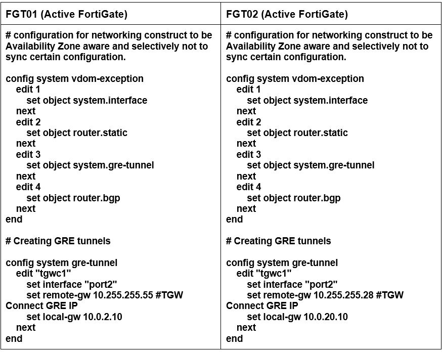
Figure 3 – Establish AWS Transit Gateway Connect GRE tunnels.
- Configure GRE tunnel interface IPs using the FortiGate graphical user interface (GUI).
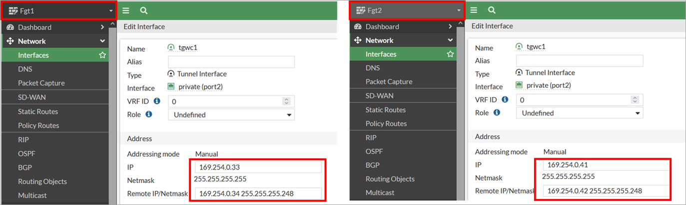
Figure 4 – FortiGate GRE tunnel interface configuration.
- Configure static routes for the Transit Gateway CIDR range, which is required for FortiGate to reach the Transit Gateway CIDR using a private interface (port 2) elastic network interface (ENI).
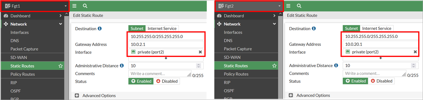
Figure 5 – FortiGate static route configuration.
- Configure border gateway protocol (BGP) on the FortiGate appliances to establish dynamic routing. Note that only the primary FortiGate (with role active) will have the GRE tunnel and BGP status showing as “Up.”
- On failure, the secondary appliance (with role passive) becomes the active unit and establishes connectivity via the secondary GRE tunnel and BGP connection.

Figure 6 – Establish AWS Transit Gateway Connect BGP sessions.
- Configure the firewall policy to permit GRE and BGP traffic on both FGT1 and FGT2 appliances in addition to north-south traffic policy. All traffic is permitted in this example for simplicity but is not recommended for production deployments where least privilege access should be implemented.